One of the reasons why most rainwater systems use too much power is because because the pump is too big. For other reasons see Rainwater – Pump Issues
Most pump suppliers and design charts will specify a larger pump than you really need (They sell a more expensive pump, It’s less likely that the pump will be returned because it isn’t big enough, and they aren’t paying the power bill)
If you want to pick the most economic pump here is how to go about it.
Instantaneous Flow
What is the most flow you need at any one time. Here are some figures for typical house fittings.
Fitting
Flow Litres/min
Tap
10 to 15
Tap with Flow Restrictor
4 to 6
Low Flow Shower
7 to 9
Washing Machine*
4 to 10
Dishwasher
4 to 6
Toilet
3 to 5
Garden Sprinkler**
10 to 15
*To get to the lower figure you will need to close the supply valve this will add a few minutes to the wash but will help with issues like Water Hammer.
**It’s really better to irrigate the garden with a separate pump.
Add together the highest flow rate fittings that you think you will want to run together, which will give you a Total Flow Rate ‘Q’
Pressure
You need to aim for a pressure at the fitting of around 150kPa (15m of Head)
To get this pressure you need to:
Measure the height of the furthest fitting above the lowest level in the tank ‘Hs)
Calculate the Pressure Loss ‘Hf‘ due to Friction in the pipes See table below
Max Flow Rate Litres/min
Hf m head per 100m of pipe
20
25
32
40
12
10.9
3.7
1.2
0.4
24
13.4
3.9
1.3
36
8.3
2.8
The Required Pump Pressure is then calculated from:
Required Pump Head ‘P‘ m = 15 +Hs + Hf
Or Required Pump Head ‘P‘ KPa = 150 +(Hs +Hf)) x 10
Ordering
To order a pump you just need to quote the Total Flow and Required Pump Head
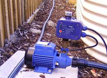
When you are ordering a pump think about getting a Pressure Tank
The vast majority of new houses will have a conventional (sometimes called a Gravity, or Open system) storm water drainage system discharging to either:
Public Surface Water Drain – Typically in Eastern States
Soakwells on Sandy Sites – Mainly in WA
With a conventional system like this the pipes are either vertical or at a slope towards the discharge point.
A feature of this system is that when there is no flow all the pipes are empty.
Advantages
Simple and inexpensive to design and construct.
If well designed, and constructed, the speed of flow in the pipes will prevents silting and subsequent blockage.
Disadvantages
This type of system can look very untidy when taking water to a Rainwater Tank that is some way from many of the downspouts (It results in lengths of pipes suspended in mid air)
Difficult to transfer water to a discharge point that is above the ground level of the building, although below the gutter level. A problem often encountered on demolition and rebuild projects and battleaxe blocks.
If you are planning a rainwater tank or are having problems with getting storm water to a suitable discharge point you could consider a Closed System
It’s important to make sure you are getting the right type of pipes and fittings that will be underground…..you don’t want to be digging up you garden, or paths, in case of blockages.
Pipes
Some plumbers will want to use, and bury, 90 mm diameter rainwater pipes, basically plastic downpipes.
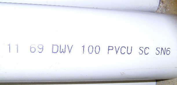
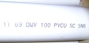
You need to make sure you are getting as a minimum 100 mm PVC pipes rated as DWV.(Stands for Drainage, Waste and Vent).
The reasons are:
The 90 mm pipe is thin walled and can be easily deformed once buried. This means you lose capacity without realising it. The DWV is a much thicker and thus stronger pipe.
Although the increase in pipe diameter is fairly small the flow capacity of the larger pipe is over 40% higher. That makes a difference in storm conditions.
Pipes are normally marked at 1m intervals with the type, manufacturer, nominal diameter, material, and the Standards reference (AS/NZS1260).
One of the problems during a new house construction is that concrete tend to fill underground pipes, causing blockage.
A hydraulic impact cutter can remove concrete in drains and sewers.
Other problems include leaking or burst pipes caused by corrosion, tree roots, and collapsed pipes.
Roots tend to grow toward the direction of the water so a loose connecting or weak point in the underground pipes triggers tree roots to wrap around them until they burst.
That’s why the design of the pipe system is crucial to ensure a problem-free plumbing.
They should be away from trees and other structures to avoid these problems.
A qualified and experienced plumber will detect common leak indicators in the underground pipes and repair them. They’ll test the repair and fill the trench.
Bends
Bend refers to a term for any change or offset of direction in the pipes, which includes elbows.
They’re fabricated as per piping specification requirement.
Elbows come in standard or pre-fabricated and are available off the shelf.
Bends are available in 4 different angles for DFW pipes as follows: 15 degrees, 30 degrees, 45 degrees and 90 degrees.
Although 90 degree bends are available, I would NOT install them underground due to the blockage risk….. If you need a 90 degree change of direction underground:
For a drain or a sewer use a junction pit.
For a charged (pressure) rainwater system use two 45 degree bends with an inspection ‘T’ in the middle.
In a post on Outlet Location I talked about improving the water quality by avoiding taking water from the bottom of the tank.
This post shows how you can keep the floating particles on the top of the water out of your supply for just a few dollars.
Mid Level Outlet
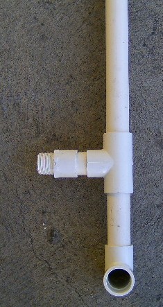
In order to avoid the floating particles you need to take the water from at least 100mm below the surface, and avoid siphoning the water out of the tank.
To do this you will need:
A valve socket, to be screwed into the existing tank outlet.
A 90 degree bend.
2 ‘T’ junctions.
Around 2.5 of plastic pipe.
I would recommend at least 25mm dia pipe although larger would be better if it will fit in the tank outlet.The components are assembled as shown in the photo on the right.
The top pipe should finish above the water level of the tank when full.
In normal use the water is taken from the level of the Bottom ‘T’. When the level drops to the level of the horizontal pipe the air coming down the vertical pipe will act to stop a siphon forming and sucking down the top level of water.
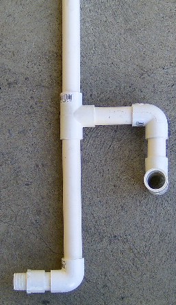
Low Level Outlet
The only additional component if you are going to improve the existing low level out let is an extra 90 degree band.
It is however assembled in a slightly different order as shown in the photo on the right.
The only problem with this arrangement is it means that the Water below the outlet cannot be accessed unless you have an extra bottom outlet. (or use a submersible pump dropped into the tank)
Something you might never have thought about when thinking about the sort of roof that you want on your new house is Risk.
Low Risk
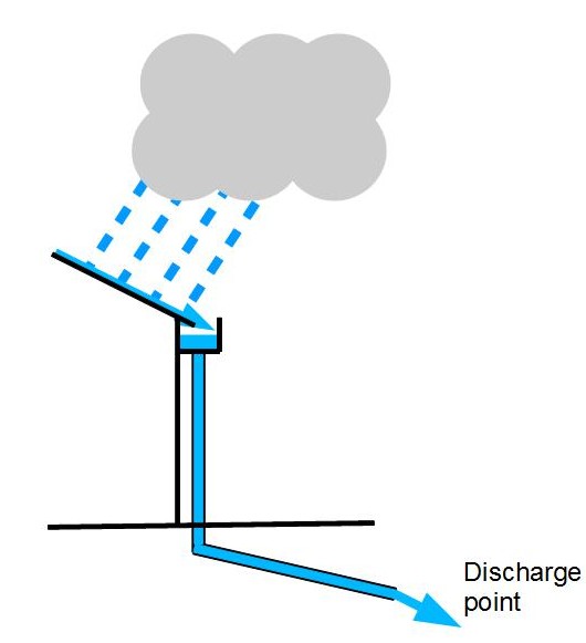
A conventional roof which slopes to the outside can be considered to be a low risk roof.
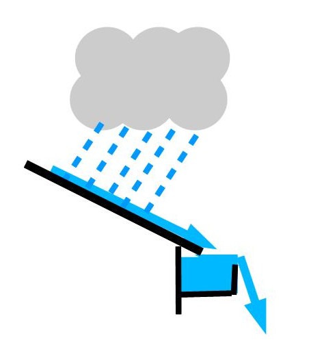
In severe weather conditions heavy rain can exceed the capacity of the gutters and the downspouts causing an overflow. Blockages in the gutters and downspouts will also cause overflows
With a conventional roof the gutters will overflow to the outside of the building as shown in the diagram to the right avoiding damage to the inside of your home.
High Risk
A couple of other roof choices are of much higher risk.
These are:
Roof with Parapet
This sort of construction is used to give the effect of a Flat Roof, although there is actually a pitched roof behind the parapet wall.
As you can see from the diagram in severe rain, or a blockage, there is a greater risk of the overflow occurring inside the house.
Butterfly Roof
A butterfly roof is when two pitched roof panels fall to a central box gutter.
Again you can see the real risk of overflow into the house in case of problems.
What the Regulations Say
For a ‘High Risk Roof’ the regulations require the roof plumbing to be be designed for a heavier storm (1 in 100 years), rather than 1 in 20 years for a ‘Low Risk Roof’.
A ‘High Risk Roof’ drainage system also require special overflows to be installed.
This link will show you how to calculate the rate of rainfall used in design: Rainfall Intensity
In practice I hear of a number of non complying plumbing installations, and many of the overflows I see don’t look to have adequate capacity.
Did anyone check your roof drainage calculations? ……..If I chose a high risk roof it would be something I wanted to be checked thoroughly.
In Understanding Tank Water Quality I explained that the typical tank outlets is located close to the bottom of the tank. This takes the dirtiest water from the bottom of the tank,rather than the cleanest water near the top.
So what can you do?
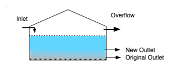
Well the simplest solution is to put a second outlet further up the tank, as shown below.
The top outlet is then used for the supply to the house, while the lower outlet is used to supply a garden tap.
The following schematic shows a typical installation.
Normal operation is with Valve 1 open supplying the pump, and Valve 2 open supplying a garden tap. Valve 3 is left shut.
The garden top would only have the pressure of the tank so it could only be used for low pressure jobs like filling a watering can. At extra cost you could add a separate pump.
When the tank level drops below the top outlet Valve 3 can be opened to supply the pump. Although this water is taken from the bottom of the tank most of the substandard water should have been drained off to the garden.
The outlet should also be on the opposite side of the tank to the Inlet.
Outlet Modification shows a low cost modification to further improve the quality
In Understanding Tank Water Quality I explained that most tank inlets mix the dirtier incoming water with the cleanest water at the top of the tank.
So what can you do?
Its not as simple as just extending the inlet pipe to the bottom…..The jet of water will create turbulence in the anaerobic zone with the most silt. This will mix this very dirty water with the better quality water higher up the tank, creating problems.
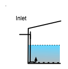
One solution to reduce turbulence is:
Put a ‘T junction at the inlet. (This will allow the falling water to draw in air to further oxygenate the fresh water.)
Install a downpipe to just below the bottom of the tank.
Put two 90 degree bends on the bottom so the flow is directed upwards with the outlet being about 150mm from the bottom. (above the anaerobic zone)
You can get a special fitting for the bottom of the pipe but my solution below will probably be cheaper and just as effective.
Put a ‘T’ at the bottom of the downpipe and have two bends so the flow into the tank from each pipe is half that of the single pipe. (See photo )
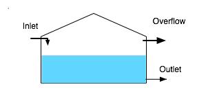
The drawing on the right shows a fairly typical rainwater tank layout.
I have seen lots of tanks set up like this and have also seen this layout in tank supplier’s brochures.
The set up is probably OK for garden watering and toilet flushing but not much else………………………..”So what are the Issues?”
Variable Water Quality From Top to Bottom
Even with ‘leaf screens’ and ‘first flush divertors’ there is going to be some particles in the water coming of your roof, These particles will either be lighter than water and float to the top, or heavier than water and sink to the bottom.
The smaller the particle the longer it will take to sink to the bottom.
The 2nd diagram shows how the water quality varies through the tank a few days after it has rained.
There are some particles floating on the surface.
There is some material close to the bottom which can include rotting organic matter. Sometimes called the Anaerobic zone.
The water between the bottom and the top gradually improves as the height increases with the best water being about 1 cm below the surface.
Problems
Because of the variable water quality problems are:
The outlet is close to the zone of worst water quality.
When it rains the turbulence from the inlet mixes the tank which then takes time to settle.
The overflow takes some of the better quality water.
Over the next few weeks I will provide information about ways of improving the water quality in your tank.