Construction – Holes In Timber Frames

The house frame has all been completed, and inspected . . . . and then some idiot plumber drills holes in the frame like this!

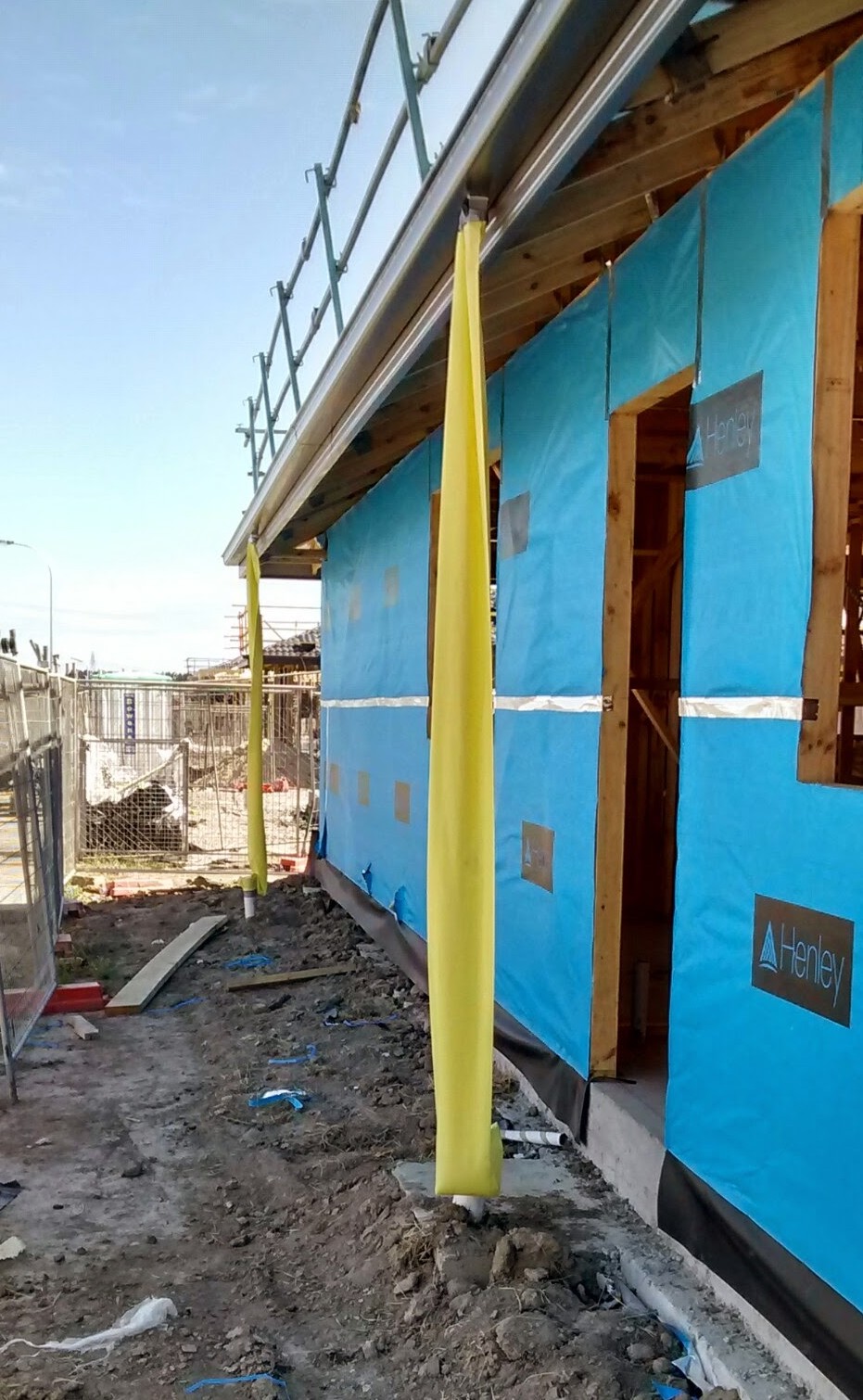
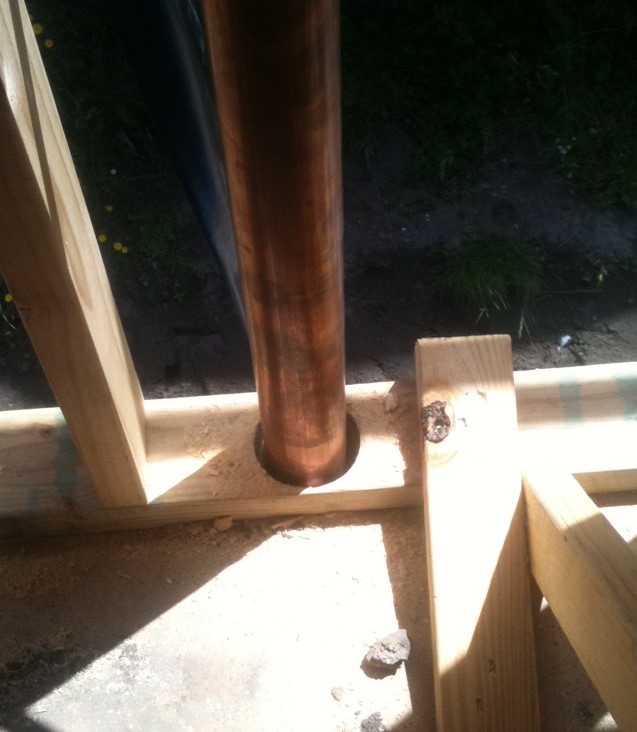
Right through the bottom plate, and the top plate, of both storeys of the house!

Holes are often drilled in:

  • Studs*
  • Plates*
  • Beams /Joists

* see Basic Timber Frame  for an explanation of these terms.

If it’s not the plumber drilling through the frame it might be the electrician or air conditioning installer.

So what is allowable?

Holes in Studs, and Plates, of Wall Frames

  • Only on wide face of Stud.
  • Maximum size of hole 25mm dia
  • Must be in centre of Stud.
  • No closer than 3 x width of stud from any trench cut into stud.

Holes in Solid Beams

Horizontal holes no more than 25mm dia

  • Maximum of 3 in a 1.8m length of span.
  • Each hole must be at least equivalent to the beam depth from the adjacent hole.

Horizontal holes no more than 50mm dia

  • Minimum spacing of 1.8m along span.
  • Maximum dia no more than 1/4 beam depth. (for a 150mm deep beam maximum diameter will be 37mm)
  • Must be located in middle third of beam depth.

Vertical Holes

  • Maximum diameter 1/4 of width of beam
  • Must be in centre of beam
  • Minimum spacing 6 x width

NB

  1. When considering spacing, a knot in the wood is considered the same as a hole.
  2. For holes in Manufactured Timber Joists you should check with the manufacturer’s Website.

Further Reading

Australian Standard AS1684 Timber Framing

The Australian House Building Manual by Allan Staines, published by Pinedale Press.


See Structural Frame for more posts


Concrete Cracking – Pattern of Fine Cracks

Some people refer to these as  ‘spiderweb’ cracks but the technical name is ‘mapping cracks’.

That’s because they can look like a street map.

Generally they are much more obvious after rain as water seeps doown into the cracks.

These cracks are typically only 2-3mm deep and are as a result of the surface concrete shrinking more, and sometimes faster, than the underlying concrete.

The reasons for this greater/faster shrinkage include:

■ Adding water to the mix, when the delivery truck arrives on site, to improve concrete workability.
■ Starting finishing while ‘bleed water’ (standing water after placed concrete levelled) is on the surface
■ Sprinkling cement powder to soak up ‘bleed water’.
■ Letting the surface dry without Proper Curing .

Although the cracking does spoil the look, it is a cosmetic issue and it doesn’t significantly affect the strength of the concrete.

See Concrete for more posts.


Concrete Curing Membrane

Photo thanks to www.civilblog.org

One simple thing to improve the quality of concrete is to use a spray applied curing membrane. . . it’s a pity that this techniques doesn’t seem to be used much in Australian domestic building.

Purpose of Membrane

These membranes main purpose is to prevent the loss of moisture during the Curing Period.

Some membranes can also help with surface hardening the concrete and help prevent dust.

Types of Membranes

When looking at types of membranes you will find

  • Water based
  • PVA based
  • Chlorinated-rubber based
  • Resin based.

In my opinion a water or PVA based membrane will be quite suitable for the typical house slab or driveway.

A further consideration is whether to use a clear membrane or a white pigmented material.

Unless I was using the compound on a coloured concrete, or an exposed aggregate finish, I would go for the white pigmented finish. It has the following advantages:

  • The colour makes is easier to check the whole surface has been covered evenly.
  • The white colour, which will fade during the curing period, will reflect more sun reducing the temperature of the concrete during the cure.

Always check that the membrane coating is  compatible with anything that will be later applied to the concrete, such as flooring materials. 

Further Information

For further information you can check the following websites


See Concrete for More Posts

Brick Ties

Veneer galvanised brick tie

Brick ties, although small, have an important part to play in the structural strength of your new home.

  • In brick veneer construction, ties are used to pass all the sideways forces across the cavity (such as from wind) to the frame.
  • For double brick construction the ties share the forces between the leaves.
  • They prevent lateral movement at expansion and articulation joints.
  • Special ties also connect walls where bonding of masonry is not practical.

Effectiveness

Probably the biggest test of brick walls in Australia was the 1989 Newcastle (NSW) earthquake. . . . Generally brick walls survived well except where there were problems with the ties such as:

  • Rusted through galvanised ties;
  • Ties not properly connected;
  • Missing ties;
  • Incorrect ties used.

Types

Ties are available in a wide range of types and in various strengths such as heavy, medium and light duty. (Ancon Building Products have a very informative downloadable guide)

The tie illustrated above is a galvanised stamped steel plate tie, used to connect the brickwork to a frame. The tie is nailed to the frame (through the hole at the top) and the corrugated end is incorporated into the mortar joint of the brickwork. The section of tie which spans the cavity is shaped to shed water.

In the case of a double frame construction a wire tie with loops at each end, or a figure of 8 shape,are the common choices of ties.

Common Materials are:

  • Galvanised Steel – Most common type.
  • Stainless Steel – For high exposure locations or very long life. (Seem expensive but only a small component Thof overall building  cost)
  • Plastic – Mainly for acoustic applications.

Spacing

Check with your Structural Engineer but for a typical medium duty application:

  • Vertical Spacing 600mm  but 300mm around openings
  • Horizontal Spacing  600mm for Double Brick  OR every main stud for Brick Veneer (normally 450mm for external walls and 600mm for internal walls

More information can be found in the Australian Standard AS3700 .


See Bricks for more posts


Timber Frames – Packing

An issue with timber frames is making sure that the frame is bedded securely on the floor slab. . . . You don’t want movement of the frame when the house is completed!

Flatness of the Slab

You may think the building slab looks flat but in practice very few slabs are perfectly level.

The Guide to Standards and Tolerances states “Generally the floor shall be within + or- 10mm of the finished floor level in any room and within +or- 5mm in a 3m length.”

So when the frame is put on the floor it could look something like the exaggerated sketch below.

Making Sure The Frame Is Stable

The key issue is to make sure that the frame is fully supported under the stud positions otherwise the studs can move vertically.

That means that packing will need to be fixed under the bottom plate at the locations shown by the red arrows above.

Packing can be made from hardboard, MDF, Plywood, metal, formica, or specialised plastic packers (sometimes called shims).

It is important that the packers should be secure and non compressible.

They should also not project beyond the bottom plate, otherwise they may affect the later secure fastening of plasterboard and skirting boards.


See Structural Frame for more posts


Temporary Down Pipes

A great way to stop the building site from becoming water logged is for the builder to install temporary down pipes as soon as the roof has been covered.

Although this is generally good practice it is really important if you are building on Reactive Clay as it will minimise the occurrence of Soil Heave damaging the slab.

Basically the temporary down pipes are a polythene tube (see photo) which is taped to the gutter outlet and the pipe that the final downspout will be connected to.

As you can see the temporary down pipes aren’t going to cost much.

If I was looking round a large development area at the houses being constructed seeing temporary downpipes in place would certainly make me think that the builder was more committed to quality


For Similar Posts see Getting it Right


Builder’s Christmas Shutdown

Every Year I hear complaints of “Everything has stopped on my House Build for a month

What can make it worse is when the builder ‘Tries’ to claim an ‘Extension of Time’ for the Build.

What Does The Contract Say?

Well I have looked through the HIA Contract for my last build and here are the relevant parts.

Schedule 1*

Schedule 1 is the place that the builder states the time for completion of the build.

It specifically provides the builder with the opportunity to show how many days are included for; Weekends, public holidays,  rostered days off, and other foreseeable delays. (Christmas, and Easter, shutdowns come round every year! . . . .You can’t tell me they are not foreseeable!)

Builders Right to Extensions of Time (Clause 34*)

Acceptable reasons for ‘Extensions of Time’are:

  • The owner requests a variation.
  • Suspension due to the Owner Breaching the Contract.
  • Inclement Weather. (Bad weather during a foreseeable closure doen’t count! . . . unless it is at the end of the period and leaves the site too wet for a quick start.)
  • Disputes with neighbours that are not the builders fault.
  • Civil Commotion or industrial action (Annual shutdowns are not industrial action!)
  • Anything not done by the owner or their agents.
  • Approval delays that are not the builders fault. (It is foreseeable that there may be a delay in getting approval over the Christmas and Easter periods!)
  • Anything the builder can’t control (By making appropriate allowance in Schedule 1 the Builder controls the situation!)

What You Can Do

Before Signing The Contract

Ask the Builder to provide in writing the details of the allowance for foreseeable delays to Schedule 1*

If The Builder Claims For A Christmas, Or Easter, Shutdown Extension.

Write back stating “Building Industry  Shutdowns during the main Holiday Periods are entirely foreseeable events that should have been allowed for in the Build Period”.

* In your contract documents the numbers may be different but you should find similar sections.


See Contract Conditions for more posts


Concrete Paving – Key Joints

I have previously talked about the importance of Well Designed Concrete Paving so here is a product that will help you achieve that.

It’s  called the Connelly Key Joint

A galvanised steel strip forms a keyway in the vertical face of the joint which means that reinforcement isn’t needed across the joint in footpath slabs.

In driveway slabs dowel bars can be used to provide additional support across the joint.

Installation

The ‘Key Joint’ is fixed installed on the base to form contraction and construction joints, and ensures that  the concrete cracks at the joint in preference to in the middle of the slab.

The concrete is then laid and finished to the top of the ‘Key Joint’.

As the concrete ‘Cures‘, and shrinks, it breaks cleanly away from the ‘Key Joint’ to form a suitable joint surface.

Photographs

(NB as these photos were taken the day before concrete was to be poured so Bar Chairs had not been installed )

Photo 1 – Contraction Joint

This shows an unreinforced contraction joint which will occur in the middle of the pour to ensure that the concrete will crack at the joint.

You can see that the reinforcement has been stopped approx 40mm from the joint.

The pegs which are driven into the base to hold the ‘Key Joint’ in place can also be seen.


Photo 2 – Construction Joint

This shows  construction joint with dowels for additional joint support, after placing of the first slab.

Again you can see that the main slab reinforcement has been stopped approx 40mm from the joint.

The dowels are pushed  through ‘Knock Outs’ in the ‘Key Joint’. (N.B the dowel spacing is greater than the mesh spacing)

Although it has not been done in this case I prefer alternate ends of the dowels to be painted with bitumen to reduce the grip of the concrete on the dowel. (This helps reduce the risk of shrinkage crack other than at the joint)

Edge Formwork

The Key Joint can also be used as a permanent form work at the edge of slabs, preferably with the key on the outside.


N.B, I have received any financial benefit for this posting or am in any way connected with the manufacturers or suppliers of this product.


For more posts see Concrete


Sleeper Wall – Appearance


Have you thought about about concrete for your sleeper wall?

As well as plain concrete it’s possible to have a wide variety of other finishes, and colours.

Here is an interesting ‘Stacked Stone’ appearance wall I saw the other week.

Some of the other options include ‘Exposed Aggregate’ and ‘Split Stone’ and even ‘Wood Grain’.

Just do a ‘GOOGLE Images‘ Search for “Concrete Sleeper Retaining Walls” and you should find a range of styles.

An advantage of concrete sleepers is they don’t rot, which means a quality lasting finish with no maintenance!

Prices start at around $25 for a 2.00m x 200mm panel, rising to $50 for some of the more attractive finishes.


See Retaining Walls for more information


Silt Pits

Any drainage system should have silt pits at regular intervals.

This includes both stormwater systems and agricultural drains.

In the case of the above photo this is a combination drain and grate  silt pit. (As the water  can become stagnant this is a potential breeding ground for mosquitos!)

The pit may be either circular or square, with a base below the level of the inlet and outlet pipes. This means any sand or silt that gets into the drainage system will get washed into the silt pit where it falls to the bottom and can be easily removed.

Collecting the silt in the pit stops it being washed further along the system eventually causing a blockage,

The following diagram illustrates how the silt pit works.

Part of your ongoing property maintenance, after you move in, should to check the silt pits every year. If the silt gets up to the outlet pipe the pit will need to be cleaned.


For more posts see Drainage


Exit mobile version