Rainwater – Pressure Tank

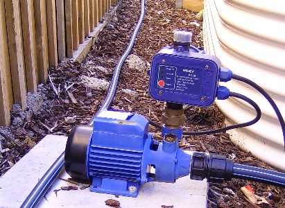
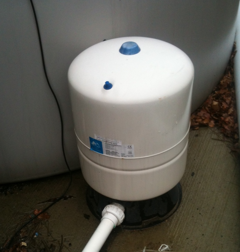
A pressure tank,  which I think is the most important upgrade to a standard rainwater supply system,  looks like the photo on the right.

Small tanks are mounted on the pump, larger tanks like this one are on the ground.

Key Features

What you get is a cylindrical storage tank storage tank with an internal membrane.

The top part of the tank, above the membrane, is filled with compressed air.

The bottom part of the tank will be filled with water by the pump from a connection at the tank base.

In the top half of the tank there is an air valve where you can check the air pressure and add more air if necessary.

How It Works

 The top of the tank is pre-charged with air to a pressure slightly lower  than the ON setting of the pressure switch.

When the pump starts water is pumped into the tank compressing the air until the maximum pressure is reached.

If you turn on a tap  the compressed air will push water out of the tank until the  tank is almost empty (when the pressure will have dropped to the minimum level)

If you use less water than that stored in the tank the pressure doesn’t drop enough so the pump doesn’t start.

Once the pressure switch turns the pump back on, the pump fills the tank while at the same time supplying water to your system. Even if you turn the tap of the pump will continue to run until the tank reaches maximum pressure.

Tank Sizing

Although very small tanks are available about the smallest tank I would recommend would be an 18litre tank, which would give a flow volume of around 5litres between pump starts.

A 35litre tank with a flow volume of around 11litres between pump starts would ensure a toilet flush would not exhaust the tank.

Why Should You Get A Pressure Tank?

It can cost more than some pumps to buy the pressure tanks so why buy it is an important question.
To find out the problems with a standard set up see the post “Rainwater – Pump Issues
The pressure tank should:

    • Double, or even treble the life of the pump, by reducing the number of pump starts and pump run time.
    • Significantly reduce the power usage by ensuring the pump mainly runs at the design rate.
    • Reduces the noise nuisance by less frequent pump runs.


For more posts about tank water see the Rainwater Section under the Sustainability Tab


Rainwater – Pump Issues


This photo shows a fairly typical pump installation.

An electric pump with pressure sensor control. It’s even got a fairly large diameter flexible suction hose between the tank and the pump.

So…..What are the issues?

Well water is an incompressible substance so every time some water leaves the system the pressure drops enough to trigger the sensor and the pump starts…………..That happens whether you are having a shower, putting a splash of water on your hands, or even a couple of drops dripping from a slightly leaky toilet valve.

This leads to Three Issues.

Efficiency

Electric pumps are designed to pump efficiently at their designed rate. If you are using water at a slower rate than the design rate the pump wastes energy trying to pump at its designed flow.

A lot more power is used to start the pump then when the pump is running for some time.

A Recent Study for the CSIRO showed that a typical domestic rainwater system used more energy than traditional centralised water treatment and distribution systems.

Pump Life

The main thing that wears pumps out is continually starting rather than running.

Noise

Because the pump runs frequently you are more likely to notice the noise. If you have got a leaking tap or toilet valve it will be starting up several times through the night.

Solutions

If you have got a large block with a slope of several metres it may be possible to install a header tank. This solution however is not normally possible for most of us.

The best solution for the average house is to upgrade by installing a Pressure Tank. Follow the link to find out more.


For more posts about tank water see the Rainwater Section under the Sustainability Tab

Reducing External Noise


It’s not always possible to build in a quiet area so there are a number of techniques for reducing noise that you can use in your new home.

Here is a quick review of the options:

  • Minimising  windows facing the noise. OK  as long as the noise source isn’t on the North side otherwise you loose the effect of sunlight in the house.
  • Screen walls. These reflect sound. If you are going for this approach at the front of the house put some thought into the design of the wall. A plain wall just looks ugly.
  • Buffer zones. I’ve previously talked about Buffer Zones in relation to heating and cooling but they can work well in keeping some rooms quieter.
  • Soft landscaping. Absorbs sound, rather than paving which reflects sound. If possible a landscaped bund (low embankment) can be effective.
  • Roofing material.  Tiles will absorb more noise than a colorbond roof.
  • Acoustic Plasterboard. It’s possible, on special order, to get a range of Plaster boards including ones with a denser core that help to reduce sound transmission. A second layer of plasterboard at a different thickness to the original can help.
  • Ceiling  and wall insulation. Ordinary heat insulation batts will absorb noise but for the best performance it is better to use ƒspecialist acoustic insulation.
  • Glazing. Thicker glass will help but double glazing with a larger air will give better performance. The use of  laminated glass can also improve performance.
  • Curtains Heavy curtains can be effective, when they are closed.
  • Solid Doors. Better performance than the standard lightweight doors.
  • Windows and door seals. Need to be  properly fitted, and maintained.
  • ƒRefrigerated Air Conditioning.  Unlike evaporative cooling this doesn’t rely on open windows.
  • Sound absorbing materials Although acoustic tiles, carpets, underlays don’t stop noise getting in they will absorb it better than hard surfaces like tiles or wood floors.

To get effective performance  will require a range of the above options rather than a single ‘Magic Bullet’.

When you are considering these options its also worth bearing in mind that most of these improvements will also improve the thermal performance of your new house.


For more posts about plans see the Design Category.

To save money on Heating and Cooling see Insulation


Conventional Drainage

The vast majority of new houses will have a conventional (sometimes called a Gravity, or Open system) storm water drainage system discharging to either:

    • Public Surface Water Drain – Typically in Eastern States
    • Soakwells on Sandy Sites – Mainly in WA


With a conventional system like this the pipes are either vertical or at a slope towards the discharge point.

A feature of this system is that when there is no flow all the pipes are empty.

Advantages

  • Simple and inexpensive to design and construct.
  • If well designed, and constructed,  the speed of flow in the pipes will prevents silting and subsequent blockage.

Disadvantages

  • This type of system can look very untidy when taking water to a Rainwater Tank that is some way from many of the downspouts (It results in lengths of pipes suspended in mid air)
  • Difficult to transfer water to a discharge point that is above the ground level of the building, although below the gutter level. A problem often encountered on demolition and rebuild projects and battleaxe blocks.

If you are planning a rainwater tank or are having problems with getting storm water to a suitable discharge point you could consider a Closed System


Also see Underground Pipes


Underground Pipes

It’s important to make sure you are getting the right type of pipes and fittings that will be underground…..you don’t want to be digging up you garden, or paths, in case of blockages.

Pipes

Some plumbers will want to use, and bury, 90 mm diameter rainwater pipes, basically plastic downpipes.

You need to make sure you are getting as a minimum 100 mm PVC pipes rated as DWV.(Stands for Drainage, Waste and Vent).

The reasons are:

      • The 90 mm pipe is thin walled and can be easily deformed once buried. This means you lose capacity without realising it. The DWV is a much thicker and thus stronger pipe.
      • Although the increase in pipe diameter is fairly small the flow capacity of the larger pipe is over 40% higher. That makes a difference in storm conditions.

Pipes are normally marked at 1m intervals with the type, manufacturer, nominal diameter, material, and the Standards reference (AS/NZS1260).

This is printed on the pipe every 1m.

Protect Underground Pipes

It’s important to protect your underground pipes.

One of the problems during a new house construction is that concrete tend to fill underground pipes, causing blockage.

A hydraulic impact cutter can remove concrete in drains and sewers.

Other problems include leaking or burst pipes caused by corrosion, tree roots, and collapsed pipes.

Roots tend to grow toward the direction of the water so a loose connecting or weak point in the underground pipes triggers tree roots to wrap around them until they burst.

That’s why the design of the pipe system is crucial to ensure a problem-free plumbing.

They should be away from trees and other structures to avoid these problems. 

You can use an experienced plumber to help protect your underground pipes.

A qualified and experienced plumber will detect common leak indicators in the underground pipes and repair them. They’ll test the repair and fill the trench.

Bends

Bend refers to a term for any change or offset of direction in the pipes, which includes elbows.

They’re fabricated as per piping specification requirement.

Elbows come in standard or pre-fabricated and are available off the shelf. 

Bends are available in 4 different angles for DFW pipes as follows: 15 degrees, 30 degrees, 45 degrees and 90 degrees.

Although 90 degree bends are available, I would NOT install them underground due to the blockage risk….. If you need a 90 degree change of direction underground:

      • For a drain or a sewer use a junction pit.
      • For a charged (pressure) rainwater system use two 45 degree bends with an inspection ‘T’ in the middle.

Rainwater Tank – Outlet Modifications

In a post on Outlet Location I talked about improving the water quality by avoiding taking water from the bottom of the tank.

This post shows how you can keep the floating particles on the top of the water out of your supply for just a few dollars.

Mid Level Outlet

In order to avoid the floating particles you need to take the water from at least 100mm below the surface, and avoid siphoning the water out of the tank.

To do this you will need:

    • A valve socket, to be screwed into the existing tank outlet.
    • A 90 degree bend.
    • 2 ‘T’ junctions.
    • Around 2.5 of plastic pipe.

I would recommend at least 25mm dia pipe although larger would be better if it will fit in the tank outlet.The components are assembled as shown in the photo on the right.

The top pipe should finish above the water level of the tank when full.

In normal use the water is taken from the level of the Bottom ‘T’. When the level drops to the level of the horizontal pipe the air coming down the vertical pipe will act to stop a siphon forming and sucking down the top level of water.

Low Level Outlet

The only additional component if you are going to improve the existing low level out let is an extra 90 degree band.

It is however assembled in a slightly different order as shown in the photo on the right.

The only problem with this arrangement is it means that the Water below the outlet cannot be accessed unless you have an extra bottom outlet. (or use a submersible pump dropped into the tank)


For more about tank water quality see Rainwater Safety


Slab Insulation

I have previously posted about the relatively small heat loss from a slab on ground
But what if you have got in slab heating, or just want to minimise heat loss/gain from your house?

Before Construction

This sketch shows the placement of the insulation, if you can arrange for the builder to install it before construction.

The way this is installed is the insulation foam is installed inside the slab formwork.

A 40mm foam board with an R value of 1.0 will typically reduce the heat loss from the slab by 50%.

If you have a small builder or are having a custom home built this should be possible……some project builders however will probably be unwilling to do this installation.

After Construction

If you want to insulate after construction this detail is as effective as the previous method.

It works by using the soil as insulation.

Although soil is not a great insulator by stopping the heat escaping upwards 1m of  soil will provide a R value around 1.


See Insulation for similar Posts

For Posts about Green Building see Sustainability


Roof Choice – Risk

Something you might never have thought about when thinking about the sort of roof that you want on your new house is Risk.

Low Risk

A conventional roof which slopes to the outside can be considered to be a low risk roof.

In severe weather conditions heavy rain can exceed the capacity of the gutters and the downspouts causing an overflow. Blockages in the gutters and downspouts will also cause overflows

With a conventional roof the gutters will overflow to the outside of the building as shown in the diagram to the right avoiding damage to the inside of your home.

High Risk

A couple of other roof choices are of much higher risk.

These are:

Roof with Parapet

This sort of construction is used to give the effect of a Flat Roof, although there is actually a pitched roof behind the parapet wall.

As you can see from the diagram in severe rain, or a blockage, there is a greater risk of the overflow occurring inside the house.

Butterfly Roof

A butterfly roof is when two pitched roof panels fall to a central box gutter.

Again you can see the real risk of overflow into the house in case of problems.


What the Regulations Say

For a ‘High Risk Roof’ the regulations require the roof plumbing to be be designed for a heavier storm (1 in 100 years), rather than 1 in 20 years for a ‘Low Risk Roof’.

A ‘High  Risk Roof’ drainage system also require special  overflows to be installed.

This link will show you how to calculate the rate of rainfall used in design: Rainfall Intensity

In practice I hear of a number of non complying plumbing installations, and many of the overflows I see don’t look to have adequate capacity.

Did anyone check your roof drainage calculations? ……..If I chose a high risk roof it would be something I wanted to be checked thoroughly.


Also see Whats on the Roof

and Want a Flat Roof


Rainwater Tank – Outlet Location

In Understanding Tank Water Quality I explained that the typical tank outlets is located close to the bottom of the tank. This takes the dirtiest water from the bottom of the tank,rather than the cleanest water near  the top.

So what can you do?

Well the simplest solution is to put a second  outlet further up the tank, as shown below.


The top outlet is then used for the supply to the house, while the lower outlet is used to supply a garden tap.

The following schematic shows a typical installation.

Normal operation is with Valve 1 open supplying the pump, and Valve 2 open supplying a garden tap. Valve 3 is left shut.

The garden top would only have the pressure of the tank so it could only be used for low pressure jobs like filling a watering can. At extra cost you could add a separate pump.

When the tank level drops below the top outlet Valve 3 can be opened to supply the pump. Although this water is taken from the bottom of the tank most of the substandard water should have been drained off to the garden.

The outlet should also be on the opposite side of the tank to the Inlet.
 

Outlet Modification shows a low cost modification to further improve the quality

To help you pick a tank see Round or Slimline Tanks


Rainwater Tank – Inlet Improvements

In Understanding Tank Water Quality I explained that most tank inlets mix the dirtier incoming water with the cleanest water at the top of the tank.

So what can you do?

Its not as simple as just extending the inlet pipe to the bottom…..The jet of water will create turbulence in the anaerobic zone with the most silt. This will mix this very dirty water with the better quality water higher up the tank, creating problems.

One solution to reduce turbulence is:

  1. Put a ‘T junction at the inlet. (This will allow the falling water to draw in air to further oxygenate the fresh water.)
  2. Install a downpipe to just below the bottom of the tank.
  3. Put two 90 degree bends on the bottom so the flow is directed upwards with the outlet being about 150mm from the bottom. (above the anaerobic zone)

You can get a special fitting for the bottom of the pipe but my solution below will probably be cheaper and just as effective.

Put a ‘T’ at the bottom of the downpipe and have two bends so the flow into the tank from each pipe is half that of the single pipe. (See photo )


To help you pick a tank see Round or Slimline Tanks


Exit mobile version