Waffle Pod Raft Slab

A ‘Waffle Pod’ slab is now probably the most common Concrete ‘Raft’ House base.

It has generally taken over from the Conventional Raft Foundation.

It’s an example of composite construction with polystyrene pods forming the voids in the underside of the concrete ‘Waffle’.

This photo shows some of the pods, with the reinforcement fixed over them, prior to placing the concrete.

Advantages

  • Cost
  • No trenches resulting in:
    • Simpler excavation; and
    • Flat sub-base means site is easier to keep dry than trenches that collect water.
  • Waffle Pods bring house further out of ground so in an area that is wet the higher the better.
  • Better insulation from the ground meaning the floor will warm up quickly from cold when you put the heating on. (especially if you go for in slab heating)

Disadvantages

  • More susceptible to bad workmanship – If the pods move during placing of the concrete.
  • More susceptible to bad drainage which can lead to soil heave if building on reactive clay
  • Lower thermal mass so less suited to passive solar design.
  • Thinner slab (typically 75mm rather than 100mm) means may it not be as resistant to point loads such as jacking a car. Some people specify 100mm thickness for the garage floor.
  • A thicker overall slab may be needed if you want Floor Drains (To allow for the dropped floor in those rooms)

Problem Sites

If  your block has difficult ground conditions its still possible to use a waffle pod slab with:


Also see Ground Conditions
 

Building On Fill – Concrete Piers

Its not unusual for the Site Investigation Report for your new house to reveal loose fill materials above a more stable clay or rock.

It might also reveal the soil is in poor condition.

To deal with the problem of building on poor ground concrete piers are a commonly used solution.

These are basically a hole that is excavated through the poor material and into the top of good ground. The hole is then backfilled with concrete to the level of the underside of the slab.

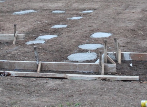
When they are finished you have a flat site with piers visible as concrete ‘pads’  (like the photo below), ready for the slab to be constructed

You don’t have to have Concrete piers over the whole site, just the parts where there will be fill, or weaker soil between the bottom of the slab and the stronger soils.

The following diagram shows a typical slab on a cut and fill site with piers excavated through the fill to the good ground.

See the following link for an alternative to Concrete Piers: Screw Piles.

The Slab over the piers is likely to be either a Waffle Pod Raft or a Conventional Raft Slab

When the site investigation indicates fill the builder will often put in a Provisional Sum for the estimated metresdepth of concrete piers.

At the time of construction they will drill down to  good ground in the fill areas and calculate the actual metres you will need to pay for.

If your whole house is on ‘Controlled Fill‘ You may not need to use concrete piers.


Lots more information in the anewhouse Guide to Buying a Block for only $4

See Ground Conditions for more about your new house foundations.


Conventional Raft Slab

A ‘Conventional’ Raft Slab is a concrete base laid directly on a compacted base.

It is strengthened by cutting trenches in the base and adding reinforcement.

These ‘thickened beams’ are formed at the edges and also under loadbearing walls.

This photo shows the base covered in poly , reinforcement placed and edge forms in position ready for placing of concrete.

Advantages

  • Higher thermal mass, as it incorporates the thermal mass of ground  so better suited to passive solar design.
  • Less susceptible to bad workmanship by concretors
  • More resistant to point loads, such as jacking a car.
  • A thicker overall slab makes it easier if you want Floor Drains (To allow for the dropped floor in those rooms)

Disadvantages

  • Generally uses more concrete, than ‘Waffle Pod Slabs‘, with more waste as volume is less predictable
  • Rain can cause construction delays as the trenches for the beams can fill with water
  • More complicated excavation can lead to additional cost


Also see Ground Conditions


Building On Sand

Building on sand at first seems to be an issue…… although I have heard it said that sand is actually the easiest ‘soil to build on.

If you live in West Australia there is a good chance that your house will be on sand so there is plenty of experience around .

Raft Foundations


Modern raft foundations actually cope with this any problems of building on sand quite well.

This is because the raft foundation spreads the load of the building over the whole area of your house which matches the weight carrying capacity of the sand very well.

This is much better than concentrating the loads on the wall foundations.

If you are building on sand a waffle pod raft foundation is probably the best way to go.

This is because the waffle pod doesn’t rely on any excavated trenches of the conventional raft slab to form the beams that gives the base its rigidity.

Soil Erosion

The main concern with sand is that it is very erodible so its important to make sure that the building site is flat and there are adequate retaining walls preventing the sand being eroded on the downhill side of the house………and eventually from under the house!

This is particularly the case if you are building a property with a sea view, you wouldn’t like to finish like this *house!

*photo courtesy of Australian Coastal Society


See Ground Conditions for more about your new house foundations.


What’s The Side View Of Your House?


When most people look at a display home the two first considerations are:

  1. The Floor Plan.
  2. The Front Elevation. (Like the impressive facade in this photo)

Sometimes that works fine when all the houses are in a line, and the same size…….but what about when the side of the house is on show?

For example:

  • Houses on corner blocks.
  • Double storey houses next to single storey houses.
  • Houses on large blocks.

The photo on the left shows the side view of the house, in the top photo, with the impressive facade.

Not only is this a lot less impressive……but as it is the view from the main road its the first impression of the house any visitor gets.

Don’t forget to think about how the sides of a house look when you are looking to build a new house!


For similar posts look in the Design Category


Roof Space – Access

One of the things that frequently gets forgotten is the hatch that gives access to the roof space.

Location

A usual location is in acorridor close to the secondary bedrooms.

It doesn’t seem that important but when you need the heating serviced, electrical alterations, plumbing alterations, etc, you are going to get tradies coming through the house.

Alternative Locations

When they have gone I often find dirty fingerprints on the hatch. . . which means I then need to get a ladder to clean the hatch.

It’s worth thinking about where you put this hatch.

If you have a single storey house the garage is probably the most convenient location followed by the laundry.

If you have got a 2 storey house an unobtrusive location may be a bit harder to find. . . . but make sure you think about it otherwise Sod’s Law says it will finish up in the worst spot.

Type and Size

If you are the sort of person who can’t throw anything away you might want some extra space for storage.

In that case perhaps you should think about a larger hatch fitted with a ladder. (The ladder in the photo is a product of the ATTIC Group which is going to cost over $1,000)

Finally

Don’t put anything heavy in the attic as the roof trusses aren’t designed for heavy loads.


For similar posts see Selection


Double Glazing or Smaller Windows?

I’ve posted on Double Glazing but that not the only way to save heat loss through windows so I thought I would do a numerical comparison of the various options for glazing treatment of windows.

In a bedroom of our last house the South facing windows were approximately 4m square (We are in Australia so these windows don’t get any sun).The  basis of my calculations is a difference of 15oC between internal and external temperature.

The equation used to calculate heat loss is:

Heat Loss  =  Area  x  Temperature Difference   x   ‘U’

for

‘U’ single glazing = 7*

‘U’ double glazing = 3*

‘U’ brick veneer = 0.51

* ‘U’ value includes effect of frame.

Option 1 Do Nothing

Heat loss through sinle glazing  =  4 x 15 x 7  =  420watts  =  0.42kw/hour

Remember this heat loss is for one room only.

Option 2 Reduce window by 40% to 2.4 m

Heat loss through single glazing  =  2.4 x 15 x 7  =  252watts  =  .25kw/hour

Heat loss through new brick vineer   =  1.6 x 15 x .51  =  12 watts  = 0.012kw/hour

Total heat loss  =  0.25kw/hr  +  0.012kw/hr  =   0.262kw/hour

With our builder this was a no cost option that has reduced the heat loss by 38%.

Option 3 Double Glazing

Heat loss through double glazing = 4 x 15 x 3 = 180watts = 0.18kW/hour

This is a heat loss reduction of 57% but at a significant cost.

Option 4 Reduce Window by 40% and Double Glazing

Heat loss through double glazing = 2.4 x 15 x 3 = 108watts = 0.108kW/hour

Heat loss through replacement brick wall = 1.6 x 15 x .51 = 12 watts = 0.012kW/hour

Total  =   0.108kW/hour  +  0.012kW/hour  =  0.12kW/hour

This final option has reduced the heat loss by over 70% and will be around 30% cheaper than double glazing the original large windows.

I hope this has given you some food for thought!

See Insulation for similar Posts

For Posts about Green Building see Sustainability

Understanding your Survey Plan

I’m used to look at survey plans but I do understand that most people struggle to understand them.

Here is a quick guide to help you understand the survey plan for your new house.

The plan below shows a survey plan, with a North Point, has been provided.for the block previously mentioned in the Title Plan Post. It doesn’t include the easement to make it easier to see the other details.

The bearing and length of each boundary are the same as the title plan in the format.

For example the North boundary is at bearing of 92 degrees 0 minutes 15 seconds (92° 00′ 15″) and 38m long.

The footpath along the front of the block and the nature strip crossover (constructed by the developer is shown, as well as an electrical pit.

TBM stands for Temporary Bench Mark.

This means the surveyor will use this feature as the level on which all other level information such as slab levels will be based.

It is normal for the TBM to be set at a round number typically either 10.000m or 100.00m.

Usually the only time the TBM’s actual height will be the correct height above Sea Level (Australian Height Datum) is when there is a risk of flooding and the floor level will need to be above the 100 year flood level.

Once the TBM has been set the surveyor calculates the surface levels of the block.

This is shown by contours, (shown dashed) which are lines of equal height.

The normal contour interval for residential block surveys is 0.2m intervals and each contour is labelled with the height it represents.

In addition to the contours the surveyor will show spot levels at the corners and sometimes in the middle of the block. (These are marked with a ‘+’ and a height)

From this drawing you can see:

  • The lowest part of the block is the South East corner at 100.00m
  • The highest part of the block is the North west corner at 100.85m
  • The block slopes upwards from the front at approx 0.53m. (around 1 in 70)
  • The block slopes upward in a Northerly direction at approx 0.30m (around 1 in 60)
  • As the contours are roughly similar spacing from each other the slopes are fairly constant.


In summary although there is a slope on the block it isn’t too severe so the site costs for dealing with the slope could be around $4- $6,000.


For more see Blocks


Wall Dimensions Standard Bricks

When you are deciding about building dimensions its better to take into account the size of building materials.

With brick veneer being so popular that means the dimensions of the bricks.

Make sure that all lengths, are based on either all complete bricks, or complete bricks with one half brick.

Similarly all heights should be based on complete bricks. Doing this has the following advantages:

  • Less wastage of bricks
  • Savings on labour due to less cutting of bricks
  • Stronger walls due to more regular bonding

The Work (design) Size of a standard brick is: 76 mm high x 230 mm long x 110 mm wide. These seem unusual dimensions but they are based on the old imperial dimensions of 3 inches by 9 inches by 4 inches.

When calculating overall wall dimensions it is normal to allow for 10mm vertical and horizontal mortar joint between bricks.

I have included  ‘Tables of Dimensions for Brickwork’ at the following two links:

Checking Bricks Meet Specification

Clay brick sizes may vary after they are fired but size variation between bricks averages out when blended properly during laying by a good bricklayer.

There are three dimensional quality levels for bricks DW1, DW2 and DW0

If you want to check the quality of the bricks the normal method of measuring is to measure 20 bricks dry stacked together against the work size of 20 Bricks.

  • Dimensional Category DW1 means the height and width will differ by less than plus or minus 50 mm from 20 times the work size, and the length will differ less than plus or minus 90 mm.
  • Dimensional Category DW2 means the height and width will differ by less than plus or minus 40 mm from 20 times the work size, and the length will differ less than plus or minus 60 mm.
  • Dimensional Category, DW0 means there are no requirements. This is usually reserved for non-standard shaped bricks and bricks that have been rumbled or otherwise distorted during the manufacturing process for aesthetic reasons.

Planning some building work in the garden? see Brick Fences

Door Opening

One of the small things that can really make a difference to your house is how doors open……..but its one thing that is frequently forgotten.

This sketch shows a typical bedroom and ensuite layout. (I know it doesn’t show the wardrobe but I’m trying to keep it simple)

A couple of things you need to think about are:

Into The Room Or Not

You will see as usual the doors to open from the corridor, into the room, and into the en-suite from the bedroom.

Particularly in the case of bathrooms and en-suites it makes a lot of sense for the door to open into the bedroom as this makes a lot more usable room in the bathroom.

It also minimises the risk of sending my wife flying if I open the door while she is at the mirror putting her make up on.

In the case of separate toilets its actually much safer to have the door open outwards. (The reason is if  an ill person passes out they are likely to fall forward against the door, stopping it being opened. . . this means getting to them can be extremely difficult)

Left Or Right Handed

How to tell – When you look at the door from the side it opens towards, and you can see the hinges…. which side are they on?

That is the hand of the door.

Looking at the door to the bedroom you will see that the door is hinged on the right as you look at it from inside the room (right handed).

This works well as the door opens against the wall. Having the door hinged from the left side doesn’t seem much different, but it means you have to walk round the door to get out.

It seems minor but in a previous house we got one door wrong and it annoyed us every day for 6 years.

Plan Doors Early!

You need to get the door opening sorted out before you can finalise your electrical plan as it will affect which side of the door you put the light switches.

Once the wires are installed and the drywall installed changing the door direction can be a major cost.

More on doors including 24 pages of Check Lists for your new house choices in the

‘Selection / Pre-Start Guide’


Exit mobile version